For our final project in ME 360, we were tasked with developing a cart that could move a 1 ft tall bar of 8020 Aluminum extrusion 5 to 10 feet forward and back without the help of support. To find the maximum acceleration I first had to draw some free-body diagrams and do some simple kinematics shown bellow.
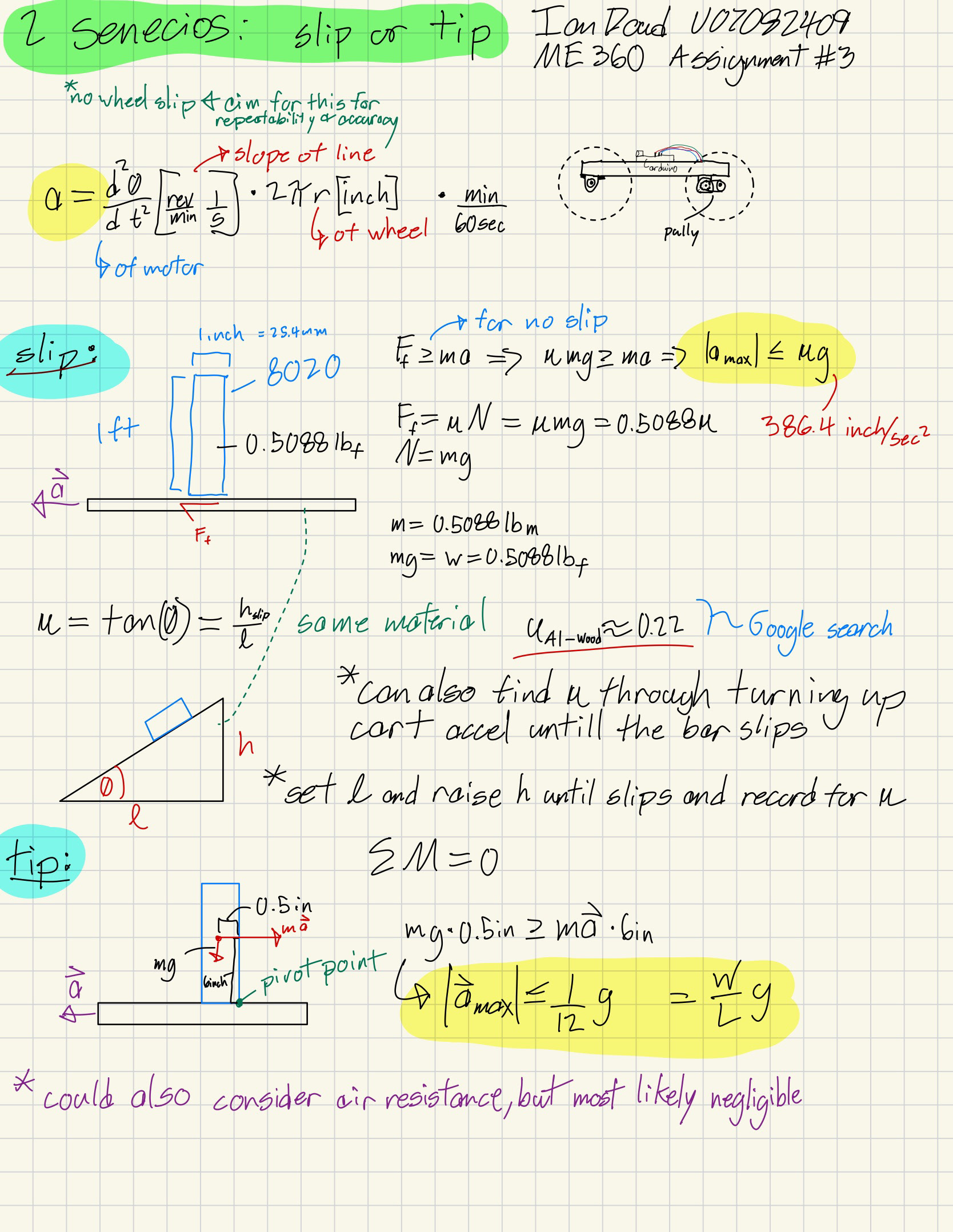
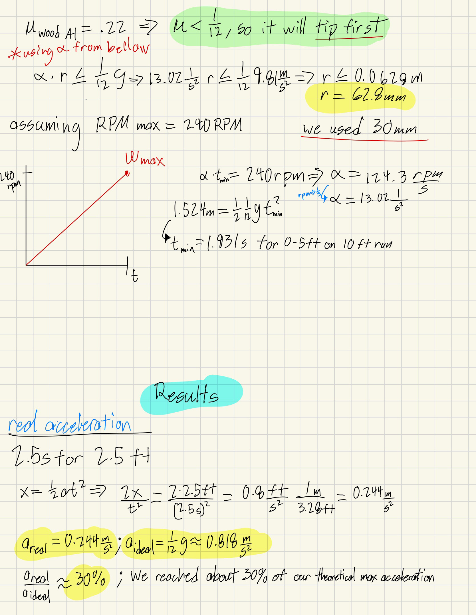
Here, we can see the two modes of failure. In a slip scenario, the bar's time rate of change of momentum exceeds the force exerted by friction, causing it to slip (a = 2.16 m/s^2). For the tip scenario, I remembered a method taught to me last year in Mechanics I. In this method, you can observe the bar as a lever acted upon by its center of mass and change in momentum about the edge at which it will tip (a = 0.818 m/s^2). From this result, we were able to calculate a minimum wheel radius of 62.8mm set by our top speed of 240rpm after 5ft of acceleration for a 10 ft run.
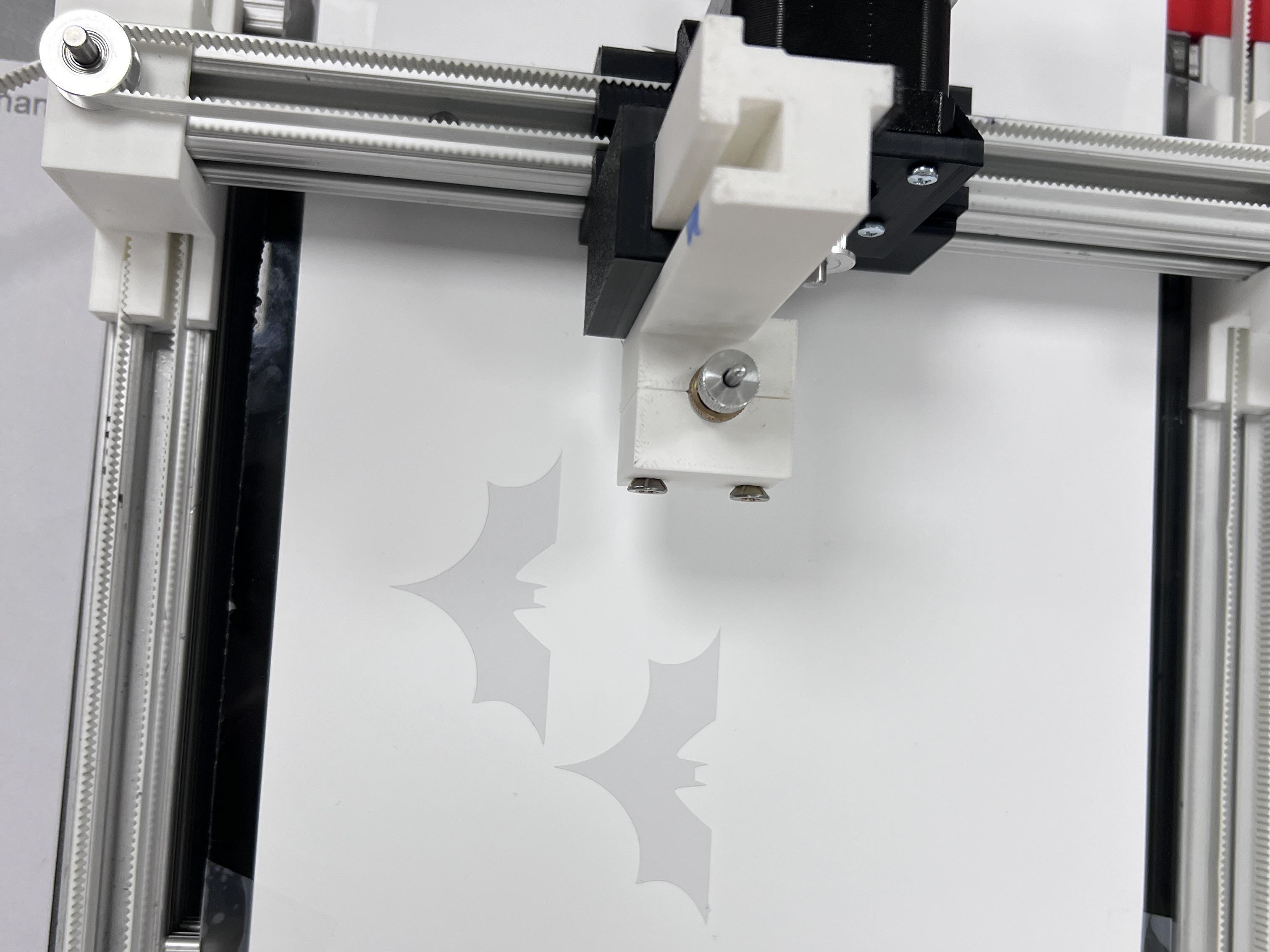
We were advised by our professor to use a slightly smaller wheel radius as he predicted we would run into problems with jerk in the system far before we could reach our maximum acceleration. We also had rubber O rings that could fit in 30mm radius wheels which would reduce vibration or jerk in the system, so we decided on that size.
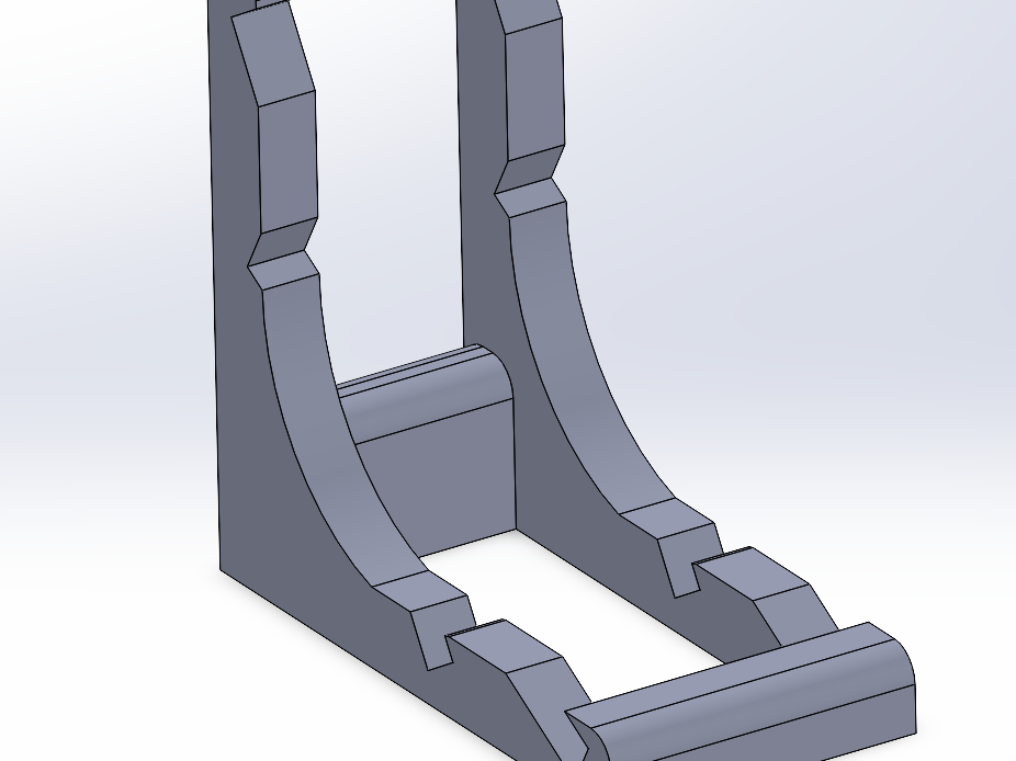
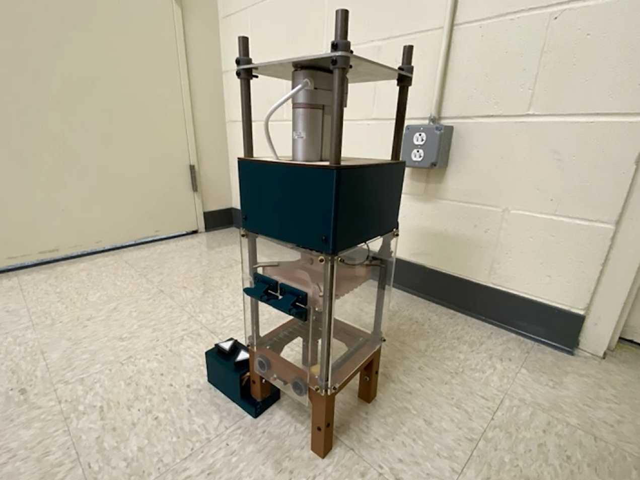
I designed the cart myself in Solidworks, keeping in mind the parts given: 2 stainless steel axles, 2 active pullies, 1 motor with a hall effect sensor, a wooden base board, and Arduino and wiring. The wheels are identical and have holes in them so threaded insert screws can secure them to the axle. I made the rest of the cart in one part so that everything would be guaranteed to be lined up because the axles rest on the 3D printed body as a friction bearing, and any misalignment would cause toque and then friction binding up the system. Also because this cart doesn't have active steering it is vital that the axles remain parallel. As I was observing other groups I found both of these issues could cause significant problems if not addressed properly. Below are some photos of the final cart assembled.

Arduino board in black, power amp in red

powered externally by a 12v dc source

motor mount spaced properly to hold tension on the belt

both boards hot glued to wooden board
The next challenge was coding the speed controller for the motor. Because it is a DC motor we can input a voltage between 0-12V and get an angular velocity, and through trial and error, we can get the correct voltage curve. However, as soon as the motor experiences a load this relationship between voltage and speed disappears. To deal with this we can use a Hall effect sensor that measures the changing currents on a magnet attached to the rotor, which we can change into an angular distance and then an angular velocity. With this information, we can compare the voltage to the angular velocity and dynamically ramp up or down the voltage in order to keep a certain speed. This is the PID control, and I am setting the derivative of voltage with respect to time, based on the speed of the motor. For the rate of change modifier or k value, I decided on 0.4 because anything greater would lead to oscillations due to second-order effects such as angular inertia. The function that archives all of this is called setRPM().
The next step was to achieve an acceleration. I achieved this with a function that produces discrete rise-over-run steps. First, you set a delta T ~100ms for delay() then you set a delta angular velocity, and it loops over calling the setRPM() function to change the angular velocity. This keeps on going until the distance has exceeded your period of constant acceleration or deceleration. This distance is measured in the same way we measure angular velocity with the Hall effect sensor. This is the final function you call and it is the travel_dis() function.
Due to problems with play and jerk in our system, we had to dial down the acceleration all the way to 30% of the theoretical max (shown under results with my initial calculations page). Even still this speed was a great achievement because we reached our max motor RPM of 240 when the cart had to travel farther than 7 ft. Below is a video we took right after official testing in which we had a similar result, and a total time of 10.84 seconds for 5 feet.
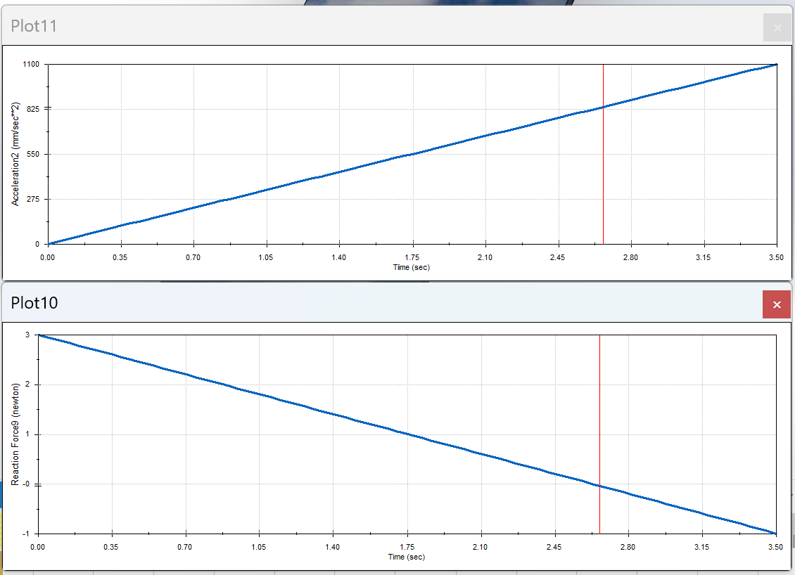
As part of our analysis, we also had to do a Solidworks simulation in which we should confirm our initial calculations of acceleration max = g/12 = 0.818m/s^2 = 818mm/s^2. Below you can see a video of the cart varying in acceleration and if we look closely at the reaction force chart and the acceleration chart we can see that when it reaches an acceleration of 0.818m/s the reaction force is zero because it is at the tipping point at which it is no longer resting on the cart. These results confirm my initial calculation at the top of the page.