working on prototype linear stage, used a threaded road and nut

Better view of prototype linear stage. We decided on using a belt and pull system because it allows for more tolerance
Here is our prototype linear stage running. We decided not to use limit switches for our final cutter, but in hindsight, one might have been useful for auto-leveling the blade head.
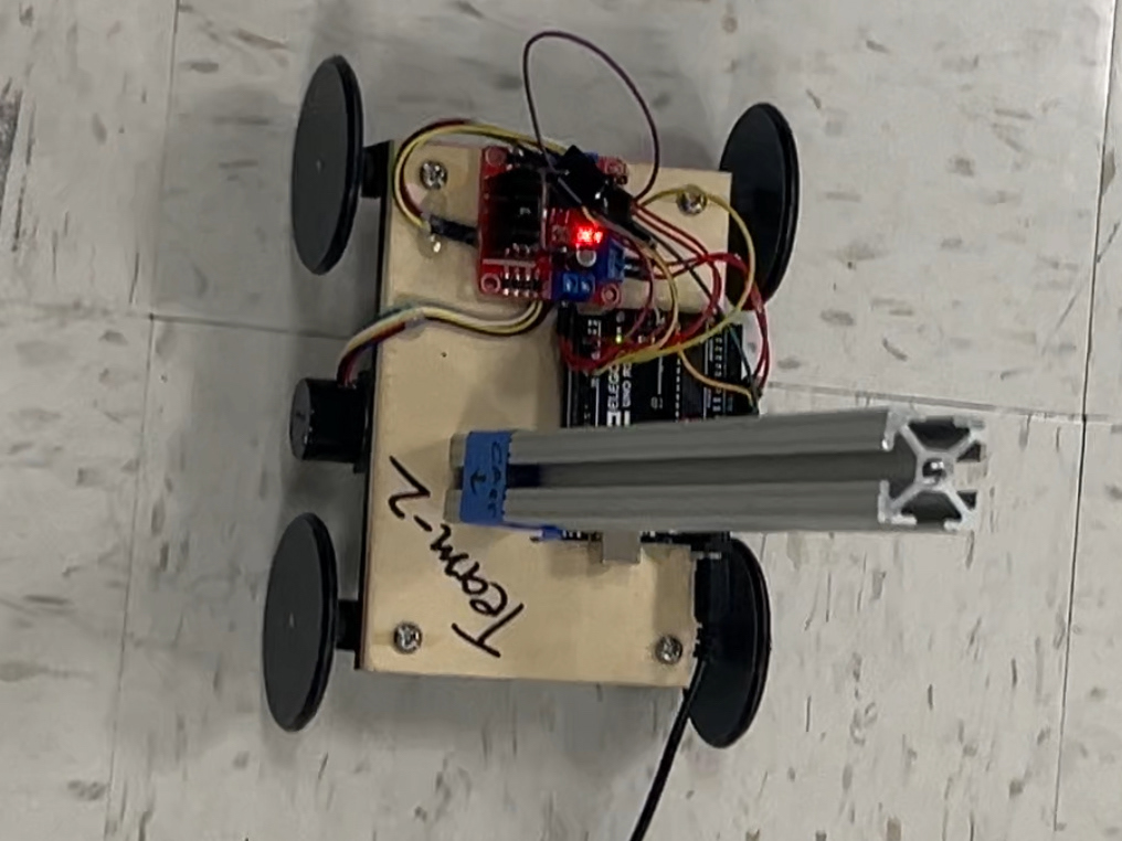
We combined our prototype linear stage with two other groups to make a full xy sweep.
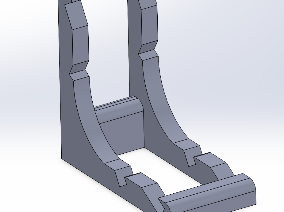
This prototype holder was used for a marker with a belt glued to it and it was our inspiration for our final cutter holder. The main difference is that ours allows for much less tolerance as it is needed to get a precise cut that only goes through half of the sticker cutter.

1) here the belt is connected to our initial test slider

2) had some problems with getting the right prints. Here the was no support made in the slicer, and other times orientation was off which made tolerances off

3) with high tension on the belt the motor mount can snap

4) design flaw, forgot offset from pully and return slot for other side of belt

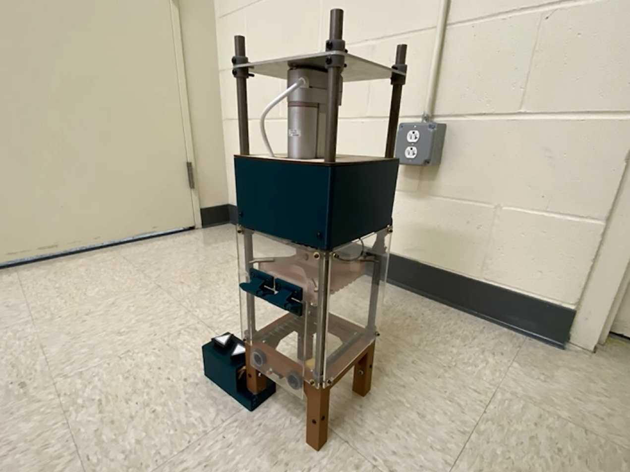
5) leveling screws

6) example of joining of 8020 with the use of a machine screws. Also profile of what slider had to fit into

7) Failed prints, 1/3 design flaws, 1/3 broken parts, 1/3 wrong print settings
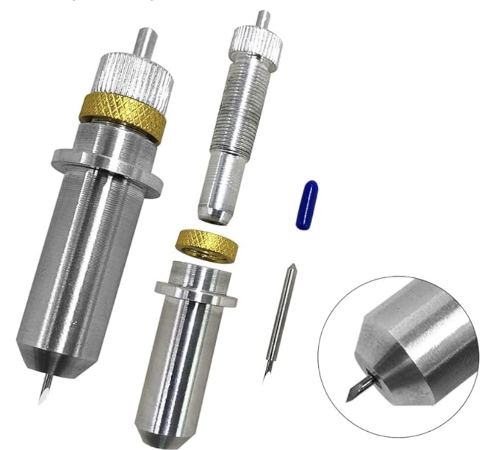
8) for our end effector/sticker cutter we used the AFUNTA Vinyl Cutter. This is a verry small drag knife meaning what ever way it is pushed it swivels with bearings to cut that way

9) dxf to g code encoder. Takes vector based files and makes a cut path with z depth retraction

10) batman stickers after they were pealed off

11) example of batman sticker
Here the depth was set right but we hadn't leveled off the build plate with the leveling screws (fig 5) so one side cuts just through the sticker and the other side cuts through both sides of the paper
Here is an example of a proper cut. First, we set the blade height above the paper and then lowered it with Repetier Host motor controller. We did this by eye, tested it by moving it in the x or y direction, examined the cut, and adjusted it accordingly. With this setup up we were able to move reliably in increments of 0.1mm and we found this to be enough precision to cut just through the sticker part of the paper.